-
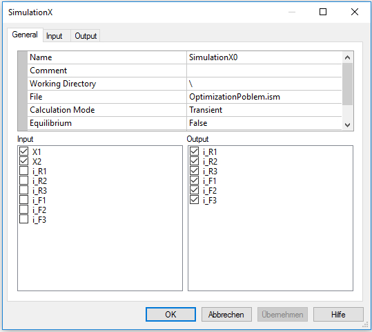
Name
It is the name of the node. This name may be defined basically once time for the entire experiment.
-
Comment
The comment for the node.
-
Working Directory
It is the working directory for the SimulationX file be opened. If the directory starts with the sign "\", it will be the relative path located on the directory of its OptiY-File (*.opy).
-
File
Select the field and press the button on the right side to open a SimulationX model. The name and the directory of the model will display in the corresponding windows. SimulationX will start at the background automatically.
-
Calculation Mode
Set calculation mode for the SimulationX model: Transien, Steady-State, Animation, FaultTree, Set Inputs, Set Inputs and Start, Get Outputs and Wait and Get Outputs. Only model parameters will be set by the option Set Inputs and only the results of the simulationX model will be read by the option Get Outputs without any model calculation. Input variables will be set by the option Set Inputs and Start and the simulation will be started without waiting to finish simulation. The simulation process will be waited to finish by the option Wait and Get Outputs. After that, the results will be read.
-
Equilibrium
If the option is True, the equilibrium of the model will be calculated before each simulation.
-
Natural Frequency
If the option is True, natural frequency and mode shapes of the model will be calculated after each simulation. First set this option to True, than reopen the SimulationX file again by the filed "File" to make results of eigenfrequencies visible for output.
-
Process
It declares the kind of the executing of the SimulationX model. There are 2 types:
-
Serial Simulation will be executed serial.
-
Parallel Simulation will be executed parallel. First, the original model will be copied to diffenent models. Than, all these models will be loaded into SimulationX and will be executed paralllel at the same time. After finished all processes, the copied models exept the original model will be closed and deleted.
-
Number of Parallel Processes
This option is visible if the process is parallel. Here, user can specify the max number of parallel executing processes. The number must be at least 2.
-
Input-Output
If the option is True, the input-output-analysis of the model will be calculated after each simulation. First set this option to True, than reopen the SimulationX file again by the filed "File" to make results of input-output-anaylsis visible for output..
-
Max. Process-Time [s]
This is the max time for execution of the process in seconds. If the execution of the process is longer than the given time, the process will be killed and the next step of optimization or design of experiment can follow. Thus, user can limited the execution time of external simulation process. If "Max Process-Time" = 0, the execution time is infinite. That means, the process will be executed naturally as long as it needed. There is no time limitation for the external process and OptiY will wait until the process finish to start the next step.
-
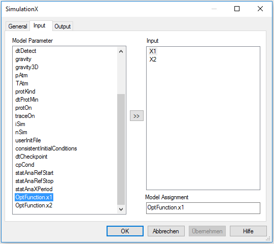
Input
The elements as nominal and stochastic parameters, transfer and output variables of the experiment can be selected as input links for the model.
-
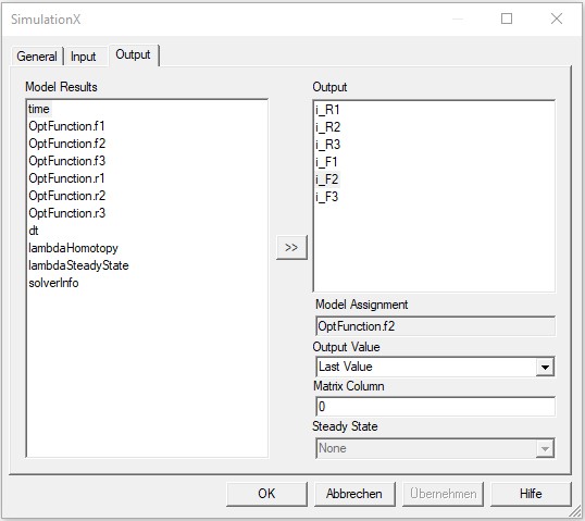
Output
The output variables of the experiment can be selected as output links for the model.